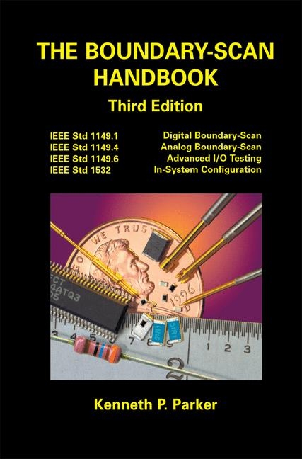
The Boundary-Scan Handbook
Kluwer Academic Publishers (Verlag)
978-1-4020-7496-7 (ISBN)
- Titel erscheint in neuer Auflage
- Artikel merken
In February of 1990, the balloting process for the IEEE proposed standard P1149.1 was completed creating IEEE Std 1149.1-1990. Later that summer, in record time, the standard won ratification as an ANSI standard as well. This completed over six years of intensive cooperative effort by a diverse group of people who share a vision on solving some of the severe testing problems that exist now and are steadily getting worse. Early in this process, someone asked me if 1 thought that the P1l49.l effort would ever bear fruit. 1 responded somewhat glibly that "it was anyone's guess". Well, it wasn't anyone's guess, but rather the faith of a few individuals in the proposition that many testing problems could be solved if a multifaceted industry could agree on a standard for all to follow. Four of these individuals stand out; they are Harry Bleeker, Colin Maunder, Rodham Tulloss, and Lee Whetsel. In that I am convinced that the 1149.1 standard is the most significant testing development in the last 20 years, I personally feel a debt of gratitude to them and all the people who labored on the various Working Groups in its creation.
1 Boundary-Scan Basics and Vocabulary.- 1.1 Digital Test Before Boundary-Scan.- 1.1.1 Edge-Connector Functional Testing.- 1.1.2 In-Circuit Testing.- 1.2 The Philosophy of 1149.1.- 1.3 Basic Architecture.- 1.3.1 The TAP Controller.- 1.3.2 The Instruction Register.- 1.3.3 Data Registers.- 1.3.4 The Boundary Register.- 1.3.5 Optimizing a Boundary Register Cell Design.- 1.3.6 Architecture Summary.- 1.3.7 Field-Programmable IC Devices.- 1.3.8 Boundary-Scan Chains.- 1.4 Non-Invasive Operational Modes.- 1.4.1 BYPASS.- 1.4.2 IDCODE.- 1.4.3 USERCODE.- 1.4.4 SAMPLE.- 1.4.5 PRELOAD.- 1.5 Pin-Permission Operational Modes.- 1.5.1 EXTEST.- 1.5.2 INTEST.- 1.5.3 RUNBIST.- 1.5.4 HIGHZ.- 1.5.5 CLAMP.- 1.5.6 Exceptions Due to Clocking.- 1.6 Extensibility.- 1.7 Subordination of IEEE 1149.1.- 1.8 Costs and Benefits.- 1.8.1 Costs.- 1.8.2 Benefits.- 1.8.3 Trends.- 1.9 Other Testability Standards.- 2 Boundary-Scan Description Language (BSDL).- 2.1 The Scope of BSDL.- 2.1.1 Testing.- 2.1.2 Compliance Assurance.- 2.1.3 Synthesis.- 2.2 Structure of BSDL.- 2.3 Entity Descriptions.- 2.3.1 Generic Parameter.- 2.3.2 Logical Port Description.- 2.3.3 Standard USE Statement.- 2.3.4 Use Statements.- 2.3.5 Component Conformance Statement.- 2.3.6 Device Package Pin Mappings.- 2.3.7 Grouped Port Identification.- 2.3.8 TAP Port Identification.- 2.3.9 Compliance Enable Description.- 2.3.10 Instruction Register Description.- 2.3.11 Optional Register Description.- 2.3.12 Register Access Description.- 2.3.13 Boundary-Scan Register Description.- 2.3.14 RUNBIST Execution Description.- 2.3.15 INTEST Execution Description.- 2.3.16 User Extensions to BSDL.- 2.3.17 Design Warnings.- 2.4 Some advanced BSDL Topics.- 2.4.1 Merged Cells.- 2.4.2 Asymmetrical Drivers.- 2.5 BSDL Description of 74BCT8374.- 2.6 Packages and Package Bodies.- 2.6.1 STD_1149_1_2001.- 2.6.2 Cell Description Constants.- 2.6.3 Basic Cell Definitions BCO to BC7.- 2.6.4 Cells BC_8 to BC_10 Introduced in 2001.- 2.6.5 User-Defined Boundary Cells.- 2.6.6 Definition of BSDL Extensions.- 2.7 Writing BSDL.- 2.8 Summary.- 3 Boundary-Scan Testing.- 3.1 Basic Boundary-Scan Testing.- 3.1.1 The 1149.1 Scanning Sequence.- 3.1.2 Basic Test Algorithm.- 3.1.3 The "Personal Tester" Versus ATE.- 3.1.4 In-Circuit Boundary-Scan.- 3.1.5 IC Test.- 3.1.6 ICBIST.- 3.2 Testing with Boundary-Scan Chains.- 3.2.1 1149.1 Chain Integrity.- 3.2.2 Interconnect Test.- 3.2.3 Connection Tests.- 3.2.4 Interaction Tests.- 3.2.5 BIST and Custom Tests.- 3.3 Porting Boundary-Scan Tests.- 3.4 Boundary-Scan Test Coverage.- 3.5 Summary.- 4 Advanced Boundary-Scan Topics.- 4.1 DC Parametric IC Tests.- 4.2 Sample Mode Tests.- 4.3 Concurrent Monitoring.- 4.4 Non-Scan IC Testing.- 4.5 Non-Digital Device Testing.- 4.6 Mixed Digital/Analog Testing.- 4.7 Multi-Chip Module Testing.- 4.8 Firmware Development Support.- 4.9 In-System Configuration.- 4.10 Flash Programming.- 4.11 Hardware Fault Insertion.- 4.12 Power Pin Testing.- 5 Design for Boundary-Scan Test.- 5.1 Integrated Circuit Level DFT.- 5.1.1 TAP Pin Placement.- 5.1.2 Power and Ground Distribution.- 5.1.3 Instruction Capture Pattern.- 5.1.4 Damage Resistant Drivers.- 5.1.5 Output Pins.- 5.1.6 Bidirectional Pins.- 5.1.7 Post-Lobotomy Behavior.- 5.1.8 IDCODEs.- 5.1.9 User-Defined Instructions.- 5.1.10 Creation and Verification of BSDL.- 5.2 Board-Level DFT.- 5.2.1 Chain Configurations.- 5.2.2 TCK/TMS Distribution.- 5.2.3 Mixed Logic Families.- 5.2.4 Board Level Conflicts.- 5.2.5 Control of Critical Nodes.- 5.2.6 Power Distribution.- 5.2.7 Boundary-Scan Masters.- 5.2.8 Post-Lobotomy Board Behavior.- 5.3 System-Level DFT.- 5.3.1 The MultiDrop Problem.- 5.3.2 Coordination with Other Standards.- 5.4 Summary.- 6 Analog Measurement Basics.- 6.1 Analog In-Circuit Testing.- 6.1.1 Analog Failures.- 6.1.2 Measuring an Impedance.- 6.1.3 Errors and Corrections.- 6.1.4 Measurement Hardware.- 6.2 Limited Access Testing.- 6.2.1 Node Voltage Analysis.- 6.2.2 Testing With Node Voltages.- 6.2.3 Limited Access Node Voltage Testing.- 6.2.4 The Mixed-Signal Test Environment.- 6.2.5 Summary.- 7 IEEE 1149.4: Analog Boundary-Scan.- 7.1 1149.4 Vocabulary and Basics.- 7.1.1 The Target Fault Spectrum.- 7.1.2 Extended Interconnect.- 7.1.3 Digital Pins.- 7.1.4 Analog Pins.- 7.2 General Architecture of an 1149.4 IC.- 7.2.1 Silicon "Switches".- 7.2.2 The Analog Test Access Port (ATAP).- 7.2.3 The Test Bus Interface Circuit (TBIC).- 7.2.4 The Analog Boundary Module (ABM).- 7.2.5 The Digital Boundary Module (DBM).- 7.3 The 1149.4 Instruction Set.- 7.3.1 The EXTEST Instruction.- 7.3.2 The CLAMP Instruction.- 7.3.3 The HIGHZ Instruction.- 7.3.4 The PROBE Instruction.- 7.3.5 The RUNBIST Instruction.- 7.3.6 The INTEST Instruction.- 7.4 Other Provisions of 1149.4.- 7.4.1 Differential ATAP Port.- 7.4.2 Differential I/O.- 7.4.3 Partitioned Internal Test Buses.- 7.4.4 Specifications and Limits.- 7.5 Design for 1149.4 Testability.- 7.5.1 Integrated Circuit Level.- 7.5.2 Board Level.- 7.5.3 System Level.- 7.6 Summary.- 8 IEEE 1149.6: Testing Advanced I/O.- 8.1 The Advanced I/O Problem.- 8.1.1 Traditional Inter-IC Communication.- 8.1.2 Advanced Inter-IC Communication.- 8.1.3 AC Coupled Signal Paths.- 8.1.4 Testing Advanced I/O.- 8.2 1149.6 Vocabulary and Basics.- 8.2.1 Advanced I/O.- 8.2.2 Signal Pin Categories.- 8.2.3 Operational Modes.- 8.3 Test Facilities for Ac Pins.- 8.3.1 Provisions for All Signal Pins.- 8.3.2 Provisions for AC Pin Drivers.- 8.3.3 AC/DC Selection Cells.- 8.3.4 Provisions for AC Pin Receivers.- 8.4 The Defect Model for 1149.6.- 8.5 The 1149.6 Test Receiver.- 8.5.1 Test Receiver Definitions.- 8.5.2 Transitions.- 8.5.3 Test Receiver DC Response.- 8.5.4 Test Receiver AC Response.- 8.5.5 Guaranteed AC-Coupling.- 8.5.6 An Integrated AC/DC Test Receiver.- 8.5.7 Initializing and Capturing Hysteretic Memory.- 8.6 BSDL Extensions for 1149.6.- 8.6.1 Boundary Registers Cells for 1149.6.- 8.6.2 STD_1149_6_2003.- 8.6.3 Example 1149.6 Device and BSDL.- 8.7 Design for 1149.6 Testability.- 8.7.1 Integrated Circuit Level DFT.- 8.7.2 Board-Level DFT.- 8.8 Summary.- 9 IEEE 1532: In-System Configuration.- 9.1 IEEE 1532 Vocabulary and Basics.- 9.1.1 Fixed System Pins.- 9.1.2 ISC System Pins.- 9.1.3 System Modal States.- 9.1.4 System I/O Behavior.- 9.1.5 ISC Pin I/O Cell Design.- 9.2 Programming Features of IEEE 1532.- 9.2.1 Core 1532 Programming Instructions.- 9.2.2 Programming a Single, Simple 1532 Device.- 9.2.3 Concurrent Programming of Multiple Devices.- 9.3 Design for IEEE 1532 Programmability.- 9.4 Epilog: What Next for 1149.1,1149.4,1149.6 and 1532?.- A. BSDL Syntax Specifications.- A.l Conventions.- A.2 Lexical elements of BSDL.- A.3 Notes on syntax definition.- A.4 BSDL Syntax.- A.5 User Package Syntax.- A.6 1149.6 Extention Attribute Syntax.
| Zusatzinfo | biography |
|---|---|
| Sprache | englisch |
| Maße | 156 x 234 mm |
| Gewicht | 747 g |
| Themenwelt | Technik ► Elektrotechnik / Energietechnik |
| ISBN-10 | 1-4020-7496-4 / 1402074964 |
| ISBN-13 | 978-1-4020-7496-7 / 9781402074967 |
| Zustand | Neuware |
| Haben Sie eine Frage zum Produkt? |
aus dem Bereich


