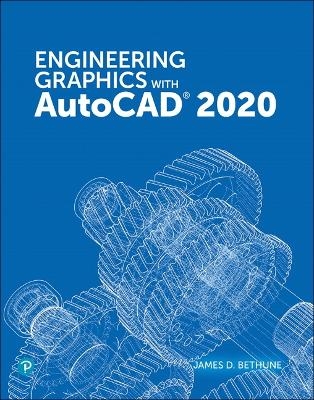
Engineering Graphics with AutoCAD 2020
Addison Wesley (Verlag)
978-0-13-556217-8 (ISBN)
- Titel erscheint in neuer Auflage
- Artikel merken
Effective pedagogy throughout the text helps students learn and retain concepts:
Step-by-step format throughout the text allows students to work directly from the text to the screen and provides an excellent reference during and after the course.
Latest coverage is provided for dynamic blocks, user interface improvements, and productivity enhancements.
Exercises, sample problems, and projects appear in each chapter, providing examples of software capabilities and giving students an opportunity to apply their own knowledge to realistic design situations.
ANSI standards are discussed when appropriate, introducing students to the appropriate techniques and national standards.
Illustrations and sample problems are provided in every chapter, supporting the step-by-step approach by illustrating how to use AutoCAD 2020 and its features to solve various design problems.
Engineering Graphics with AutoCAD 2020 will be a valuable resource for every student wanting to learn to create engineering drawings.
James D. Bethune taught drafting and Computer Aided-Design (CAD) for 39 years, twice winning the Outstanding Professor of the year award. He has a doctor’s degree in education from Boston University and has written more than 28 books on drafting and CAD. While retired from full-time teaching, Jim continues to write textbooks on CAD. An avid golfer, Jim lives in East Greenwich, Rhode Island.
Preface v
Chapter 1 Getting Started 1
1-1 Introduction 2
To Start a New Drawing 2
1-2 Tabs and Panels 5
1-3 The Command Line Box 7
1-4 Command Tools 8
1-5 Starting a New Drawing 9
1-6 Naming a Drawing 9
1-7 Drawing Units 12
1-8 Drawing Limits 15
1-9 Grid and Snap 18
1-10 Sample Problem SP1-1 20
1-11 Save and Save As 23
1-12 Open 25
1-13 Close 27
1-14 Exercise Problems 28
Chapter 2 Fundamentals of 2D Construction 31
2-1 Introduction 31
2-2 Line–Random Points 31
2-3 Erase 34
2-4 Line–Snap Points 35
2-5 Line–Dynamic Inputs 36
2-6 Construction Line 38
2-7 Circle 42
2-8 Circle Centerlines 45
2-9 Polyline 47
2-10 Spline 51
2-11 Ellipse 52
2-12 Rectangle 56
2-13 Polygon 57
2-14 Point 58
2-15 Text 59
2-16 Move 65
2-17 Copy 67
2-18 Offset 68
2-19 Mirror 69
2-20 Array 69
2-21 Rotate 72
2-22 Trim 73
2-23 Extend 74
2-24 Break 75
2-25 Chamfer 76
2-26 Fillet 77
2-27 Table 78
2-28 Exercise Problems 82
Chapter 3 Advanced Commands 93
3-1 Introduction 93
3-2 Osnap 93
3-3 Osnap–Endpoint 95
3-4 Osnap–Snap From 95
3-5 Osnap–Midpoint 97
3-6 Osnap–Intersection 97
3-7 Osnap–Apparent Intersection 98
3-8 Osnap–Center 99
3-9 Osnap–Quadrant 100
3-10 Osnap–Perpendicular 100
3-11 Osnap–Tangent 101
3-12 Osnap–Nearest 102
3-13 Sample Problem SP3-1 102
3-14 Sample Problem SP3-2 103
3-15 Grips 105
3-16 Grips–Extend 106
3-17 Grips–Move 107
3-18 Grips–Rotate 108
3-19 Grips–Scale 108
3-20 Grips–Mirror 109
3-21 Blocks 110
3-22 Working with Blocks 113
3-23 Wblock 117
3-24 Layers 120
3-25 Attributes 129
3-26 Title Blocks with Attributes 134
3-27 Edit Polyline 135
3-28 Edit Spline 136
3-29 Edit Text 138
3-30 Constructing the Bisector of an Angle–Method I 139
3-31 Constructing the Bisector of an Angle–Method II 140
3-32 Constructing an Ogee Curve (S-Curve) with Equal Arcs 141
3-33 Constructing a Parabola 142
3-34 Constructing a Hyperbola 143
3-35 Constructing a Spiral 144
3-36 Constructing a Helix 144
3-37 Designing by Using Shape Parameters 145
3-38 Exercise Problems 148
Chapter 4 Sketching 167
4-1 Introduction 167
4-2 Establishing Your Own Style 167
4-3 Graph Paper 168
4-4 Pencils 168
4-5 Lines 168
4-6 Proportions 170
4-7 Curves 171
4-8 Sample Problem SP4-1 172
4-9 Isometric Sketches 173
4-10 Sample Problem SP4-2 175
4-11 Oblique Sketches 176
4-12 Perspective Sketches 178
4-13 Working in Different Orientations 180
4-14 Exercise Problems 181
Chapter 5 Orthographic Views 195
5-1 Introduction 195
5-2 Three Views of an Object 196
5-3 Visualization 197
5-4 Hidden Lines 199
5-5 Hidden Line Conventions 199
5-6 Drawing Hidden Lines 200
5-7 Precedence of Lines 205
5-8 Slanted Surfaces 205
5-9 Projection Between Views 206
5-10 Sample Problem SP5-1 207
5-11 Compound Lines 209
5-12 Sample Problem SP5-2 209
5-13 Oblique Surfaces 211
5-14 Sample Problem SP5-3 213
5-15 Rounded Surfaces 214
5-16 Sample Problem SP5-4 216
5-17 Holes 217
5-18 Holes in Slanted Surfaces 218
5-19 Cylinders 222
5-20 Sample Problem SP5-5 223
5-21 Cylinders with Slanted and Rounded Surfaces 224
5-22 Sample Problem SP5-6 224
5-23 Drawing Conventions and Cylinders 226
5-24 Irregular Surfaces 227
5-25 Sample Problem SP5-7 228
5-26 Hole Callouts 228
5-27 Castings 231
5-28 Sample Problem SP5-8 233
5-29 Thin-Walled Objects 234
5-30 Sample Problem SP5-9 235
5-31 Intersections 236
5-32 Sample Problem SP5-10 237
5-33 Sample Problem SP5-11 239
5-34 Sample Problem SP5-12 239
5-35 Designing by Modifying an Existing Part 242
5-36 Drawing Standards 243
5-37 Third- and First-Angle Projections 245
5-38 Exercise Problems 247
Chapter 6 Sectional Views 281
6-1 Introduction 281
6-2 Cutting Plane Lines 283
6-3 Section Lines 286
6-4 Hatch 288
6-5 Sample Problem SP6-1 290
6-6 Styles of Section Lines 291
6-7 Sectional View Location 292
6-8 Holes in Sections 293
6-9 Gradients 293
6-10 Offset Sections 294
6-11 Multiple Sections 295
6-12 Aligned Sections 296
6-13 Drawing Conventions in Sections 296
6-14 Half, Partial, and Broken-Out Sectional Views 297
6-15 Removed Sectional Views 298
6-16 Breaks 299
6-17 Sectional Views of Castings 300
6-18 Exercise Problems 302
Chapter 7 Auxiliary Views 325
7-1 Introduction 325
7-2 Projection Between Normal and Auxiliary Views 326
7-3 Sample Problem SP7-1 328
7-4 Transferring Lines Between Views 329
7-5 Sample Problem SP7-2 331
7-6 Projecting Rounded Surfaces 332
7-7 Sample Problem SP7-3 332
7-8 Projecting Irregular Surfaces 334
7-9 Sample Problem SP7-4 334
7-10 Sample Problem SP7-5 335
7-11 Partial Auxiliary Views 336
7-12 Sectional Auxiliary Views 337
7-13 Auxiliary Views of Oblique Surfaces 338
7-14 Secondary Auxiliary Views 338
7-15 Sample Problem SP7-6 341
7-16 Secondary Auxiliary View of an Ellipse 343
7-17 Exercise Problems 344
Chapter 8 Dimensioning 359
8-1 Introduction 359
8-2 Terminology and Conventions 359
8-3 Linear Dimension 362
8-4 Dimension Styles 367
8-5 Units 371
8-6 Aligned Dimensions 373
8-7 Radius and Diameter Dimensions 375
8-8 Angular Dimensions 379
8-9 Ordinate Dimensions 381
8-10 Baseline Dimensions 384
8-11 Continue Dimension 385
8-12 Quick Dimension 386
8-13 Center Mark 387
8-14 Mleader and Qleader 388
8-15 Text Angle 391
8-16 Tolerances 392
8-17 Dimensioning Holes 392
8-18 Placing Dimensions 394
8-19 Fillets and Rounds 395
8-20 Rounded Shapes (Internal) 395
8-21 Rounded Shapes (External) 396
8-22 Irregular Surfaces 397
8-23 Polar Dimensions 398
8-24 Chamfers 398
8-25 Knurling 399
8-26 Keys and Keyseats 400
8-27 Symbols and Abbreviations 400
8-28 Symmetry and Centerline 401
8-29 Dimensioning to Points 401
8-30 Coordinate Dimensions 402
8-31 Sectional Views 403
8-32 Orthographic Views 404
8-33 Very Large Radii 405
8-34 Exercise Problems 406
Chapter 9 Tolerancing 427
9-1 Introduction 427
9-2 Direct Tolerance Methods 427
9-3 Tolerance Expressions 428
9-4 Understanding Plus and Minus Tolerances 429
9-5 Creating Plus and Minus Tolerances with AutoCAD 429
9-6 Limit Tolerances 432
9-7 Creating Limit Tolerances by Using AutoCAD 433
9-8 Angular Tolerances 435
9-9 Standard Tolerances 436
9-10 Double Dimensioning 437
9-11 Chain Dimensions and Baseline Dimensions 438
9-12 Tolerance Studies 440
9-13 Rectangular Dimensions 441
9-14 Hole Locations 441
9-15 Choosing a Shaft for a Toleranced Hole 442
9-16 Sample Problem SP9-1 443
9-17 Sample Problem SP9-2 444
9-18 Standard Fits (Metric Values) 444
9-19 Nominal Sizes 447
9-20 Hole and Shaft Basis 447
9-21 Sample Problem SP9-3 447
9-22 Standard Fits (Inch Values) 448
9-23 Sample Problem SP9-4 449
9-24 Preferred and Standard Sizes 449
9-25 Surface Finishes 450
9-26 Surface Control Symbols 452
9-27 Design Problems 453
9-28 Exercise Problems 459
Chapter 10 Geometric Tolerances 473
10-1 Introduction 473
10-2 Tolerances of Form 474
10-3 Flatness 474
10-4 Straightness 475
10-5 Straightness (RFS and MMC) 475
10-6 Circularity 478
10-7 Cylindricity 479
10-8 Geometric Tolerances Created by Using AutoCAD 479
10-9 Tolerances of Orientation 487
10-10 Datums 487
10-11 Perpendicularity 488
10-12 Parallelism 490
10-13 Angularism 491
10-14 Profiles 491
10-15 Runouts 493
10-16 Positional Tolerances 494
10-17 Virtual Condition 496
10-18 Floating Fasteners 496
10-19 Sample Problem SP10-1 497
10-20 Sample Problem SP10-2 498
10-21 Fixed Fasteners 499
10-22 Sample Problem SP10-3 499
10-23 Design Problems 500
10-24 Exercise Problems 503
Chapter 11 Threads and Fasteners 525
11-1 Introduction 525
11-2 Thread Terminology 525
11-3 Thread Callouts (Metric Units) 526
11-4 Thread Callouts (English Units) 526
11-5 Thread Representations 528
11-6 Orthographic Views of Internal Threads 533
11-7 Sectional Views of Internal Thread Representations 535
11-8 Types of Threads 535
11-9 How to Draw an External Square Thread 536
11-10 How to Draw an Internal Square Thread 537
11-11 How to Draw an External Acme Thread 537
11-12 Bolts and Nuts 539
11-13 Screws 539
11-14 Studs 541
11-15 Head Shapes 541
11-16 Nuts 545
11-17 Sample Problem SP11-1 548
11-18 Sample Problem SP11-2 549
11-19 Standard Screws 550
11-20 Setscrews 551
11-21 Washers 552
11-22 Keys 553
11-23 Rivets 554
11-24 Springs 555
11-25 Tool Palettes 558
11-26 Exercise Problems 561
Chapter 12 Working Drawings 571
12-1 Introduction 571
12-2 Assembly Drawings 571
12-3 Drawing Formats (Templates) 574
12-4 Title Block 576
12-5 Revision Block 578
12-6 Tolerance Block 580
12-7 Release Block 580
12-8 Parts List (Bill of Materials–BOM) 581
12-9 Detail Drawings 582
12-10 First-Angle Projection 583
12-11 Drawing Notes 584
12-12 Design Layouts 584
12-13 Sample Problem SP12-1 585
12-14 Sample Problem SP12-2 589
12-15 Sample Problem SP12-3 592
12-16 Exercise Problems 594
Chapter 13 Gears, Bearings, and Cams 617
13-1 Introduction 617
13-2 Types of Gears 617
13-3 Gear Terminology–Spur 618
13-4 Spur Gear Drawings 619
13-5 Sample Problem SP13-1 621
13-6 Sample Problem SP13-2 622
13-7 Sample Problem SP13-3 624
13-8 Selecting Spur Gears 625
13-9 Center Distance Between Gears 626
13-10 Sample Problem SP13-4 627
13-11 Combining Spur Gears 629
13-12 Gear Terminology–Bevel 629
13-13 How to Draw Bevel Gears 631
13-14 Worm Gears 633
13-15 Helical Gears 634
13-16 Racks 636
13-17 Ball Bearings 637
13-18 Sample Problem SP13-5 638
13-19 Bushings 639
13-20 Sample Problem SP13-6 640
13-21 Cam Displacement Diagrams 641
13-22 Cam Motions 643
13-23 Cam Followers 647
13-24 Sample Problem SP13-7 648
13-25 Exercise Problems 651
Chapter 14 Fundamentals of 3D Drawing 663
14-1 Introduction 663
14-2 The World Coordinate System 663
14-3 Viewpoints 665
14-4 Perspective and Parallel Grids 668
14-5 3D Modeling 670
14-6 User Coordinate System (UCS) 672
14-7 Editing a Solid Model 678
14-8 Visual Styles 679
14-9 Rotating a UCS Axis 681
14-10 Sample Problem SP14-1 683
14-11 Visual Errors 685
14-12 Sample Problem SP14-2 685
14-13 Orthographic Views 688
14-14 Line Thickness 692
14-15 Using the Thickness Command to Create Objects 695
14-16 Exercise Problems 698
Chapter 15 Modeling 703
15-1 Introduction 703
15-2 Box 703
15-3 Sphere 708
15-4 Cylinder 708
15-5 Cone 710
15-6 Wedge 712
15-7 Torus 714
15-8 Extrude 715
15-9 Revolve 717
15-10 Helix 718
15-11 Polysolid 719
15-12 Loft 720
15-13 Intersect 721
15-14 Union and Subtract 722
15-15 Solid Modeling and UCSs 725
15-16 Combining Solid Objects 727
15-17 Intersecting Solids 732
15-18 Solid Models of Castings 737
15-19 Thread Representations in Solid Models 741
15-20 List 743
15-21 Massprop 743
15-22 Face and Edge Editing 744
15-23 Exercise Problems 752
Index 781
Chapter 16 Projects (Online Only)
Appendix (Online Only)
| Erscheint lt. Verlag | 4.11.2019 |
|---|---|
| Verlagsort | Boston |
| Sprache | englisch |
| Maße | 210 x 276 mm |
| Gewicht | 1430 g |
| Themenwelt | Informatik ► Weitere Themen ► CAD-Programme |
| Technik | |
| ISBN-10 | 0-13-556217-1 / 0135562171 |
| ISBN-13 | 978-0-13-556217-8 / 9780135562178 |
| Zustand | Neuware |
| Informationen gemäß Produktsicherheitsverordnung (GPSR) | |
| Haben Sie eine Frage zum Produkt? |
aus dem Bereich


