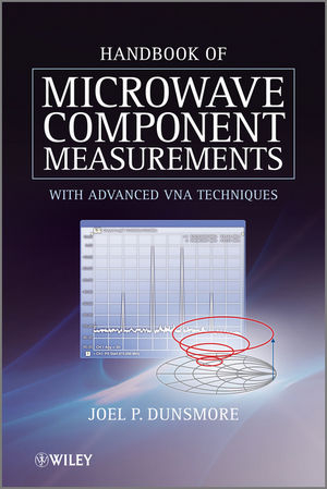
Handbook of Microwave Component Measurements
John Wiley & Sons Inc (Verlag)
9781119979555 (ISBN)
- Titel erscheint in neuer Auflage
- Artikel merken
The chapter on time-domain theory and measurements is the most complete treatment on the subject yet presented, with details of the underlying mathematics and new material on time domain gating. As the inventor of many of the methods presented, and with 30 years as a development engineer on the most modern measurement platforms, the author presents unique insights into the understanding of modern measurement theory. Key Features: * Explains the interactions between the device-under-test (DUT) and the measuring equipment by demonstrating the best practices for ascertaining the true nature of the DUT, and optimizing the time to set up and measure * Offers a detailed explanation of algorithms and mathematics behind measurements and error correction * Provides numerous illustrations (e.g. block-diagrams for circuit connections and measurement setups) and practical examples on real-world devices, which can provide immediate benefit to the reader * Written by the principle developer and designer of many of the measurement methods described This book will be an invaluable guide for RF and microwave R&D and test engineers, satellite test engineers, radar engineers, power amplifier designers, LNA designers, and mixer designers.
University researchers and graduate students in microwave design and test will also find this book of interest.
Dr. Joel P. Dunsmore, Agilent Technologies, USA Since graduating from Oregon State University with a BSEE (1982) and an MSEE (1983), Joel Dunsmore has worked for Agilent Technologies (formerly Hewlett-Packard) at the Sonoma County Site. He received his Ph.D. from Leeds University in 2004. In 2008 Joel was promoted to the rank of Agilent R&D Fellow (one of six), working for the Component Test Division.
Foreword xv Preface xvii Acknowledgments xix List of Acronyms xxi 1 Introduction to Microwave Measurements 1 1.1 Modern Measurement Process 2 1.2 A Practical Measurement Focus 3 1.3 Definition of Microwave Parameters 3 1.3.1 S-Parameter Primer 4 1.3.2 Phase Response of Networks 11 1.4 Power Parameters 13 1.4.1 Incident and Reflected Power 13 1.4.2 Available Power 13 1.4.3 Delivered Power 13 1.4.4 Power Available from a Network 14 1.4.5 Available Gain 14 1.5 Noise Figure and Noise Parameters 15 1.5.1 Noise Temperature 16 1.5.2 Effective or Excess Input Noise Temperature 16 1.5.3 Excess Noise Power and Operating Temperature 17 1.5.4 Noise Power Density 17 1.5.5 Noise Parameters 18 1.6 Distortion Parameters 18 1.6.1 Harmonics 19 1.6.2 Second-Order Intercept 19 1.6.3 Two-Tone Intermodulation Distortion 20 1.7 Characteristics of Microwave Components 22 1.8 Passive Microwave Components 23 1.8.1 Cables, Connectors and Transmission Lines 23 1.8.2 Connectors 28 1.8.3 Non-Coaxial Transmission Lines 39 1.9 Filters 42 1.10 Directional Couplers 44 1.11 Circulators and Isolators 46 1.12 Antennas 47 1.13 PCB Components 48 1.13.1 SMT Resistors 48 1.13.2 SMT Capacitors 50 1.13.3 SMT Inductors 51 1.13.4 PCB Vias 52 1.14 Active Microwave Components 52 1.14.1 Linear and Non-Linear 52 1.14.2 Amplifiers: System, Low Noise, High Power 53 1.14.3 Mixers and Frequency Converters 54 1.14.4 Frequency Multipliers and Limiters and Dividers 56 1.14.5 Oscillators 57 1.15 Measurement Instrumentation 57 1.15.1 Power Meters 57 1.15.2 Signal Sources 59 1.15.3 Spectrum Analyzers 60 1.15.4 Vector Signal Analyzers 61 1.15.5 Noise Figure Analyzers 61 1.15.6 Network Analyzers 62 References 64 2 VNA Measurement Systems 66 2.1 Introduction 66 2.2 VNA Block Diagrams 67 2.2.1 VNA Source 70 2.2.2 Understanding Source Match 72 2.2.3 VNA Test Set 77 2.2.4 Directional Devices 80 2.2.5 VNA Receivers 87 2.2.6 IF and Data Processing 90 2.2.7 Multiport Extensions 92 2.2.8 High Power Test Systems 98 2.3 VNA Measurement of Linear Microwave Parameters 98 2.3.1 Linear Measurements Methods for S-Parameters 99 2.3.2 Power Measurements with a VNA 101 2.3.3 Other Measurement Limitations of the VNA 104 2.3.4 Limitations Due to External Components 107 2.4 Measurements Derived from S-Parameters 108 2.4.1 The Smith Chart 108 2.4.2 Transforming S-Parameters to Other Impedances 114 2.4.3 Concatenating Circuits and T-Parameters 115 2.5 Modeling Circuits Using Y and Z Conversion 117 2.5.1 Reflection Conversion 117 2.5.2 Transmission Conversion 118 2.6 Other Linear Parameters 118 2.6.1 Z-Parameters, or Open-Circuit Impedance Parameters 119 2.6.2 Y-Parameters, or Short-Circuit Admittance Parameters 120 2.6.3 ABCD Parameters 121 2.6.4 H-Parameters or Hybrid Parameters 122 2.6.5 Complex Conversions and Non-Equal Reference Impedances 123 References 123 3 Calibration and Vector Error Correction 124 3.1 Introduction 124 3.2 Basic Error Correction for S-Parameters: Cal Application 125 3.2.1 Twelve-Term Error Model 126 3.2.2 One-Port Error Model 128 3.2.3 Eight-Term Error Model 128 3.3 Determining Error Terms: Cal Acquisition for 12-Term Models 130 3.3.1 One-Port Error Terms 131 3.3.2 One-Port Standards 132 3.3.3 Two-Port Error Terms 140 3.3.4 Twelve-Term to Eleven-Term Error Model 144 3.4 Determining Error Terms: Cal Acquisition for Eight-Term Models 144 3.4.1 TRL Standards and Raw Measurements 145 3.4.2 Special Cases for TRL Calibration 148 3.4.3 Unknown Thru or SOLR (Reciprocal Thru Calibration) 149 3.4.4 Applications of Unknown Thru Calibrations 151 3.4.5 QSOLT Calibration 153 3.4.6 Electronic Calibration or Automatic Calibration 153 3.5 Waveguide Calibrations 157 3.6 Calibration for Source Power 158 3.7 Calibration for Receiver Power 164 3.7.1 Some Historical Perspective 164 3.7.2 Modern Receiver Power Calibration 165 3.7.3 Response Correction for the Transmission Test Receiver 169 3.8 Devolved Calibrations 172 3.8.1 Response Calibrations 172 3.8.2 Enhanced Response Calibration 174 3.9 Determining Residual Errors 176 3.9.1 Reflection Errors 176 3.9.2 Using Airlines to Determine Residual Errors 178 3.10 Computing Measurement Uncertainties 190 3.10.1 Uncertainty in Reflection Measurements 190 3.10.2 Uncertainty in Source Power 190 3.10.3 Uncertainty in Measuring Power (Receiver Uncertainty) 191 3.11 S21 or Transmission Uncertainty 192 3.12 Errors in Phase 196 3.13 Practical Calibration Limitations 197 3.13.1 Cable Flexure 197 3.13.2 Changing Power after Calibration 198 3.13.3 Compensating for Step Attenuator Changes in Step Attenuators 200 3.13.4 Connector Repeatability 203 3.13.5 Noise Effects 204 3.13.6 Drift: Short-Term and Long-Term 205 3.13.7 Interpolation of Error Terms 206 3.13.8 Calibration Quality: Electronic vs Mechanical Kits 208 References 210 4 Time Domain Transforms 211 4.1 Introduction 211 4.2 The Fourier Transform 212 4.2.1 The Continuous Fourier Transform 212 4.2.2 Even and Odd Functions and the Fourier Transform 212 4.2.3 Modulation (Shift) Theorem 213 4.3 The Discrete Fourier Transform 214 4.3.1 FFT (Fast Fourier Transform) and IFFT (Inverse Fast Fourier Transform) 214 4.3.2 Discrete Fourier Transforms 216 4.4 Fourier Transform (Analytic) vs VNA Time Domain Transform 216 4.4.1 Defining the Fourier Transform 217 4.4.2 Effects of Discrete Sampling 217 4.4.3 Effects of Truncated Frequency 219 4.4.4 Windowing to Reduce Effects of Truncation 222 4.4.5 Scaling and Renormalization 224 4.5 Low-Pass and Band-Pass Transforms 224 4.5.1 Low-Pass Impulse Mode 224 4.5.2 DC Extrapolation 225 4.5.3 Low-Pass Step Mode 225 4.5.4 Band-Pass Mode 227 4.6 Time Domain Gating 228 4.6.1 Gating Loss and Renormalization 229 4.7 Examples of Time Domain Transforms of Various Networks 232 4.7.1 Time Domain Response of Changes in Line Impedance 232 4.7.2 Time Domain Response of Discrete Discontinuities 233 4.7.3 Time Domain Responses of Various Circuits 233 4.8 The Effects of Masking and Gating on Measurement Accuracy 234 4.8.1 Compensation for Changes in Line Impedance 234 4.8.2 Compensation for Discrete Discontinuities 236 4.8.3 Time Domain Gating 237 4.8.4 Estimating an Uncertainty Due to Masking 241 4.9 Conclusions 241 References 242 5 Measuring Linear Passive Devices 243 5.1 Transmission Lines, Cables and Connectors 243 5.1.1 Calibration for Low Loss Devices with Connectors 243 5.1.2 Measuring Electrically Long Devices 245 5.1.3 Attenuation Measurements 250 5.1.4 Return Loss Measurements 266 5.1.5 Cable Length and Delay 277 5.2 Filters and Filter Measurements 278 5.2.1 Filter Classes and Difficulties 278 5.2.2 Duplexer and Diplexers 279 5.2.3 Measuring Tunable High-Performance Filters 280 5.2.4 Measuring Transmission Response 282 5.2.5 High Speed vs Dynamic Range 287 5.2.6 Extremely High Dynamic Range Measurements 290 5.2.7 Calibration Considerations 298 5.3 Multiport Devices 299 5.3.1 Differential Cables and Lines 300 5.3.2 Couplers 300 5.3.3 Hybrids, Splitters and Dividers 303 5.3.4 Circulators and Isolators 306 5.4 Resonators 307 5.4.1 Resonator Responses on a Smith Chart 307 5.5 Antenna Measurements 310 5.6 Conclusions 312 References 313 6 Measuring Amplifiers 314 6.1 Amplifiers as Linear Devices 314 6.1.1 Pretesting an Amplifier 315 6.1.2 Optimizing VNA Settings for Calibration 317 6.1.3 Calibration for Amplifier Measurements 318 6.1.4 Amplifier Measurements 322 6.1.5 Analysis of Amplifier Measurements 328 6.1.6 Saving Amplifier Measurement Results 338 6.2 Gain Compression Measurements 342 6.2.1 Compression Definitions 342 6.2.2 AM-to-PM or Phase Compression 347 6.2.3 Swept Frequency Gain and Phase Compression 348 6.2.4 Gain Compression Application, Smart Sweep and Safe-Sweep Mode 349 6.3 Measuring High-Gain Amplifiers 354 6.3.2 Calibration Considerations 357 6.4 Measuring High-Power Amplifiers 359 6.4.1 Configurations for Generating High Drive Power 360 6.4.2 Configurations for Receiving High Power 362 6.4.3 Power Calibration and Pre/Post Leveling 364 6.5 Making Pulsed-RF Measurements 365 6.5.2 Pulse Profile Measurements 369 6.5.3 Pulse-to-Pulse Measurements 371 6.5.4 DC Measurements for Pulsed RF Stimulus 372 6.6 Distortion Measurements 374 6.6.1 Harmonic Measurements on Amplifiers 374 6.6.2 Two-Tone Measurements, IMD and TOI Definition 378 6.6.3 Measurement Techniques for Two-Tone TOI 382 6.6.4 Swept IMD 382 6.6.5 Optimizing Results 385 6.6.6 Error Correction 390 6.7 Noise Figure Measurements 391 6.7.1 Definition of Noise Figure 391 6.7.2 Noise Power Measurements 392 6.7.3 Computing Noise Figure from Noise Powers 394 6.7.4 Computing DUT Noise Figure from Y-Factor Measurements 395 6.7.5 Cold-Source Methods 397 6.7.6 Noise Parameters 399 6.7.7 Error Correction in Noise Figure Measurements 402 6.7.8 Uncertainty of Noise Figure Measurements 404 6.7.9 Verifying Noise Figure Measurements 405 6.7.10 Techniques for Improving Noise Figure Measurements 406 6.8 X-Parameters, Load Pull Measurements and Active Loads 408 6.8.1 Non-Linear Responses and X-Parameters 408 6.8.2 Load Pull, Source-Pull and Load Contours 411 6.9 Conclusions on Amplifier Measurements 416 References 417 7 Mixer and Frequency Converter Measurements 418 7.1 Mixer Characteristics 418 7.1.1 Small Signal Model of Mixers 421 7.1.2 Reciprocity in Mixers 425 7.1.3 Scalar and Vector Responses 427 7.2 Mixers vs Frequency Converters 427 7.2.1 Frequency Converter Design 428 7.2.2 Multiple Conversions and Spur Avoidance 429 7.3 Mixers as a 12-Port Device 430 7.3.1 Mixer Conversion Terms 431 7.4 Mixer Measurements: Frequency Response 434 7.4.1 Introduction 434 7.4.2 Amplitude Response 434 7.4.3 Phase Response 437 7.4.4 Group Delay and Modulation Methods 448 7.4.5 Swept LO Measurements 451 7.5 Calibration for Mixer Measurements 455 7.5.1 Calibrating for Power 455 7.5.2 Calibrating for Phase 457 7.5.3 Determining the Phase and Delay of a Reciprocal Calibration-Mixer 460 7.6 Mixers Measurements vs Drive Power 472 7.6.1 Mixer Measurements vs LO Drive 472 7.6.2 Mixer Measurements vs RF Drive Level 476 7.7 TOI and Mixers 480 7.7.1 IMD vs LO Drive Power 481 7.7.2 IMD vs RF Power 481 7.7.3 IMD vs Frequency Response 484 7.8 Noise Figure in Mixers and Converters 486 7.8.1 Y-Factor Measurements on Mixers 486 7.8.2 Cold Source Measurements on Mixers 488 7.9 Special Cases 494 7.9.1 Mixers with RF or LO Multipliers 494 7.9.2 Segmented Sweeps 495 7.9.3 Measuring Higher-Order Products 496 7.9.4 Mixers with an Embedded LO 500 7.9.5 High-Gain and High-Power Converters 503 7.10 Conclusions on Mixer Measurements 504 References 505 8 VNA Balanced Measurements 506 8.1 Four-Port Differential and Balanced S-Parameters 506 8.2 Three-Port Balanced Devices 511 8.3 Measurement Examples for Mixed Mode Devices 512 8.3.1 Passive Differential Devices: Balanced Transmission Lines 512 8.3.2 Differential Amplifier Measurements 516 8.3.3 Differential Amplifiers and Non-Linear Operation 519 8.4 True Mode VNA for Non-Linear Testing 523 8.4.1 True Mode Measurements 526 8.4.2 Determining the Phase-Skew of a Differential Device 531 8.5 Differential Testing Using Baluns, Hybrids and Transformers 533 8.5.1 Transformers vs Hybrids 533 8.5.2 Using Hybrids and Baluns with a Two-Port VNA 537 8.6 Distortion Measurements of Differential Devices 539 8.6.1 Comparing Single Ended IMD Measurement to True Mode Measurements 541 8.7 Noise Figure Measurements on Differential Devices 544 8.7.1 Mixed Mode Noise Figure 545 8.7.2 Measurement Setup 546 8.8 Conclusions on Differential Device Measurement 550 References 550 9 Advanced Measurement Techniques 552 9.1 Creating Your Own Cal Kits 552 9.1.1 PCB Example 553 9.1.2 Evaluating PCB Fixtures 554 9.2 Fixturing and De-embedding 569 9.2.1 De-embedding Mathematics 570 9.3 Determining S-Parameters for Fixtures 572 9.3.1 Fixture Characterization Using One-Port Calibrations 573 9.4 Automatic Port Extensions 578 9.5 AFR: Fixture Removal Using Time Domain 583 9.6 Embedding Port-Matching Elements 588 9.7 Impedance Transformations 591 9.8 De-embedding High-Loss Devices 592 9.9 Understanding System Stability 595 9.9.1 Determining Cable Transmission Stability 595 9.9.2 Determining Cable Mismatch Stability 596 9.9.3 Reflection Tracking Stability 597 9.10 Some Final Comments on Advanced Techniques and Measurements 598 References 599 Appendix A Physical Constants 600 Appendix B Common RF and Microwave Connectors 601 Appendix C Common Waveguides 602 Appendix D Some Definitions for Calibration Kit Open and Shorts 603 Index 606
| Erscheint lt. Verlag | 20.11.2012 |
|---|---|
| Verlagsort | New York |
| Sprache | englisch |
| Maße | 168 x 251 mm |
| Gewicht | 1224 g |
| Themenwelt | Technik ► Elektrotechnik / Energietechnik |
| ISBN-13 | 9781119979555 / 9781119979555 |
| Zustand | Neuware |
| Informationen gemäß Produktsicherheitsverordnung (GPSR) | |
| Haben Sie eine Frage zum Produkt? |
aus dem Bereich


